This post was copied from the old web site (and reformatted), it describes the steps taken by Geoff Marks dropping and refitting the keel on "Zethar" in 2004.
It is for illustrative purposes only, professional advice was taken before starting and during the job and you should do the same.
The aft keelbolt was replaced and associated repair work done in the winter of 2002/3 (click here). Epoxy filler was used at the keel but when lifted out at the end of 2003 it had not bonded to the cast iron. There was a hairline crack and after a couple of days ashore water was seeping out, so the filler was removed and the gap left to dry under a plastic sheet taped to the hull. Repeated attempts to fill the gap through the following Spring after many weeks of drying always ended in failure with the filler bubbling.

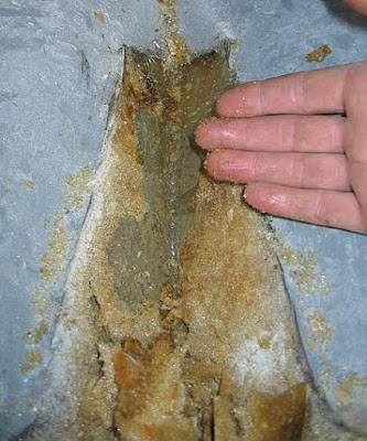
By the time we produced the bubble above, she had been out of the water for over six months. The likeliest explanation was that there was still moisture in the gap. In curing the original keel bolt problem we found that there was expanded foam under the grp cabin moulding between it and the hull at the bilge, and the concern was that the leak had let water between the hull and the liner rather than just up around the keel bolt. There were four filled holes on the moulded step for the cabin sole boards. I dug out a plug of filler and there was foam that was saturated.
With a wire and a length of rod the foam was dug out, adding four more holes to improve access.
With a length of small diameter pipe on the end of the vacuum cleaner it was a case of dig a bit, suck a bit, until as much as was possible was removed.
The only area left was under the glassed in limber pipe beneath the cockpit sole which was cut out to find more wet foam.
With the reservoir of water now gone another attempt was made to fill the keel. This time after a few days two bubbles formed and when they were cut into rusty water wept out.
The only way to properly sort this out was to drop the keel and advice from a surveyor confirmed that it was the thing to do.
The boat was moved into 'The Tent' by a very clever fully adjustable trailer best described as a giant tuning fork with wheels at the 'prongs' ends and a tractor at the other.
With blocks under the keel, the keel to hull join was ground all the way around and the keel bolts removed. She was lifted to see if the keel would drop off but of course not, so she was lifted higher by the trailer and shored up. To take her weight we used a drum forward and two drums with a railway sleeper across aft, plus blocks on top of the sleeper under the quarters and props under the bilges, and that was how she stayed suspended while the keel was off.
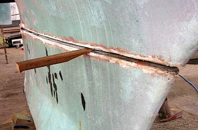
The nine inch blocks seen under the keel below were replaced with four two inch pads each end and wedges, so that we could drop the keel away from the boat by levering it up and removing a pad at a time alternately forward and aft until it sat on the floor on two inch pads. This saved having to get the trailer back again to raise the hull off the keel.
The sealer in the keel join was cut with fine toothed hacksaw blades. It was cut in about 10 inches forward and 12 inches aft until we got towards where the grp keel stub was touching the cast iron leaving no more room to cut. Softwood wedges were tried but their tips only squashed until they split so new hardwood wedges were used. With them and a 7lb sledgehammer the removal became easy. The sealer holding the keel began to split until it had cracked along half the keel which had dropped about 1/4 of an inch (6mm) at the forward end. The join crackled gently and the keel dropped half an inch onto its waiting blocks.
 |
| With the keel off the source of the problem was revealed. |
The rust around the keel bolt hole was expected but the rust at the aft end was not. It was due to the water having seeped aft from the leak and got behind the filler used to fair the keel.
After the first clean it looked much better but the mottled raised area at the aft end was rust so hard that it had to be chipped off.
The keel stub was cleaned ready to be re-joined to the keel and the picture shows the cleaning half done. The 'face off' disk used for removing the vinyl glue in the cabin was perfect for the job.
The top of the keel had a final polish the morning it was due to go back on. There are short lengths of stud in each hole to keep them clean and protect the threads.
The new lengths of threaded stud were fitted
The boat was lowered onto the studs for a dry run by dropping the boat onto the keel. Everything looked ok, so she was lifted enough to get the sealer on.

Sealer squeezed out when the boat was lowered again and this was quickly scraped off before the nuts were put on the studs and tightened, making a second 'squeeze'.
The nuts were gradually fully tightened over the next few days, a half turn at a time. Butler Mouldings used a two-part Polysulphide sealer to bed the Achilles keels. The only Polysulphide I could find was one part Boatlife Lifecalk, which is flexible, can be sanded to a smooth finish, does not have strong adhesive properties and is slow to cure. Modern sealers like Sikaflex are Polysulphates which are faster curing but have very strong adhesion.
I had been warned by the surveyor that if I used Sikaflex I would never get the keel off again. So the Lifecalk was used which cured slowly but was easily faired.
Then a coat of antifouling to finish the job.

A few thoughts.
There was rust in the area around the aft keel bolt which was anticipated from the leak, but the unexpected rust was where the water must have been seeping aft from the leak along the keel join and so behind the fairing filler at the keels edge. This was the seat of the moisture that caused the bubbles in the filler. It is impossible to say when the original leak and resulting rust occurred but it looked like it had been corroding for some time and there was the distinctive whiff of iron rusting is salt water.
The good news is that the remainder of the keel was perfect under the skin of old sealer and easily cleaned to a polished finish.
Also the keel bolts were all in excellent nick after 29 years and could have been re-used although the nuts were solidly rusted to the studs. Only the aft keel bolt has the mico-balloon block for supporting the grp. The other three bolted down onto what seemed to be solid grp which at the midship pair of bolts was about 3 inches (75mm) thick. The aft one (left) was new in 2003 but you can see there is rust on the bottom of the thread. This is because it had been taken out a couple of weeks before the pic was taken as part of a vain attempt to vent the pressure that was blowing bubbles in the keel filler.

The Ultimate Tensile Strength of mild steel is 470 Newtons per square mm with one Newton equalling 0.22 pounds of force. This calculates to a 1 inch mild steel bar being able to take a load of 23 tonnes. Of course the keel studs are threaded which reduces the cross sectional area and the threading may reduce the strength further. If we allow a reduction of 25% this still gives a theoretical ability for the four keel bolts to take a load of around 60 tons [Update 2021 by JDL: according to an on-line calculator a 1" course thread, low carbon steel bolt will support about 13.6 Tonnes, x 4 = 54.5 Tons] and this to hold a keel of just over half a ton. This is static load only and a boat pitching in a seaway is bound to increase that load although I couldn't begin to work out by how much. Would it be approaching 60 tons? I very much doubt it. I also came across something called Nevin's Rule which states that you need 1 square inch of bolt for every 1500lbs of ballast, so the Achilles 24 is well in excess of that. Please bear in mind I am not a surveyor, naval architect or mathematician so the above is only a guide - if it is correct!
With the class getting older the question of keel bolt condition is quite rightly coming up, but if the experience with the condition of these 29 year old bolts is anything to go by - I am fairly confident they are the originals - it suggests that there is not a lot to worry about.
Geoff Marks


Thanks so much for providing that wonderful account of the operation! is it just reccomended to use mild steel threaded bar and mild steel nuts? did you get them made up at a local machine shop? thanks
ReplyDeleteAs far as I am aware the author of this piece is no longer around, you are probably best to post the question on the Facebook group. I have an A9m but I believe these will be mild steel Whitworth threads, I know at least one person of Facebook will be able to confirm.
Delete